Coupling Spider: Applications, Materials, Working Principles and Selection Guide
1. Introduction: Why Coupling Spiders Matter in Industrial Power Transmission
In rotating industrial machinery, power must be transferred reliably from a prime mover—such as an electric motor or internal combustion engine—to a driven component like a centrifugal pump, gearbox, compressor, or conveyor. Even when equipment is carefully installed, slight shaft misalignments, startup torque spikes, and torsional vibrations occur during normal operation. Connecting two shafts with a completely rigid joint under these conditions transmits destructive dynamic forces directly into bearings, seals, and shaft journals.
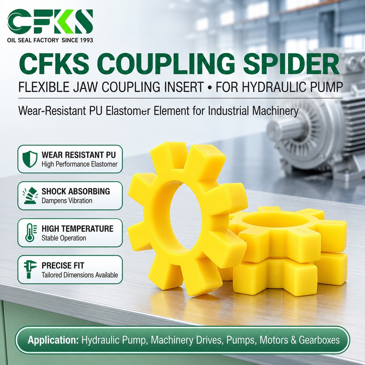
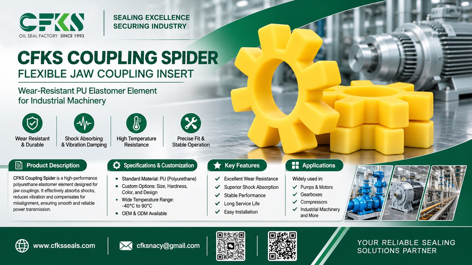
A Coupling Spider—also referred to as a jaw coupling spider, elastomeric coupling insert, or flexible coupling element—addresses this challenge. Installed between two interlocking metal coupling hubs, this star-shaped polymer component transmits rotational torque while providing controlled torsional flexibility, vibration damping, and shock absorption.
Because the coupling spider serves as a replaceable wear element, selecting the right geometry, elastomer compound, and Shore hardness directly affects drivetrain stability, component life, and maintenance efficiency. Conversely, installing an incompatible or incorrectly sized spider can lead to premature elastomer degradation, excessive backlash, abnormal vibration, and unplanned downtime.
2. What Is a Coupling Spider?
A Coupling Spider is the removable, star-shaped elastomeric center element of a jaw-type flexible coupling. To specify and source replacement components accurately, engineers and buyers must distinguish between related mechanical terms:
-
Coupling Spider (Jaw Coupling Insert / Flexible Coupling Element): The replaceable elastomeric star-shaped component featuring multiple curved lobes (legs) that fit between the metal jaws of a coupling.
-
Jaw Coupling: The complete three-piece mechanical assembly consisting of two metal hubs (commonly cast iron, sintered steel, aluminum, or stainless steel) with axially protruding jaws and one central elastomeric coupling spider.
-
Flexible Coupling: A broader engineering category of shaft couplings—including jaw couplings, gear couplings, grid couplings, and disc couplings—designed to transmit torque while accommodating limited shaft misalignment.
-
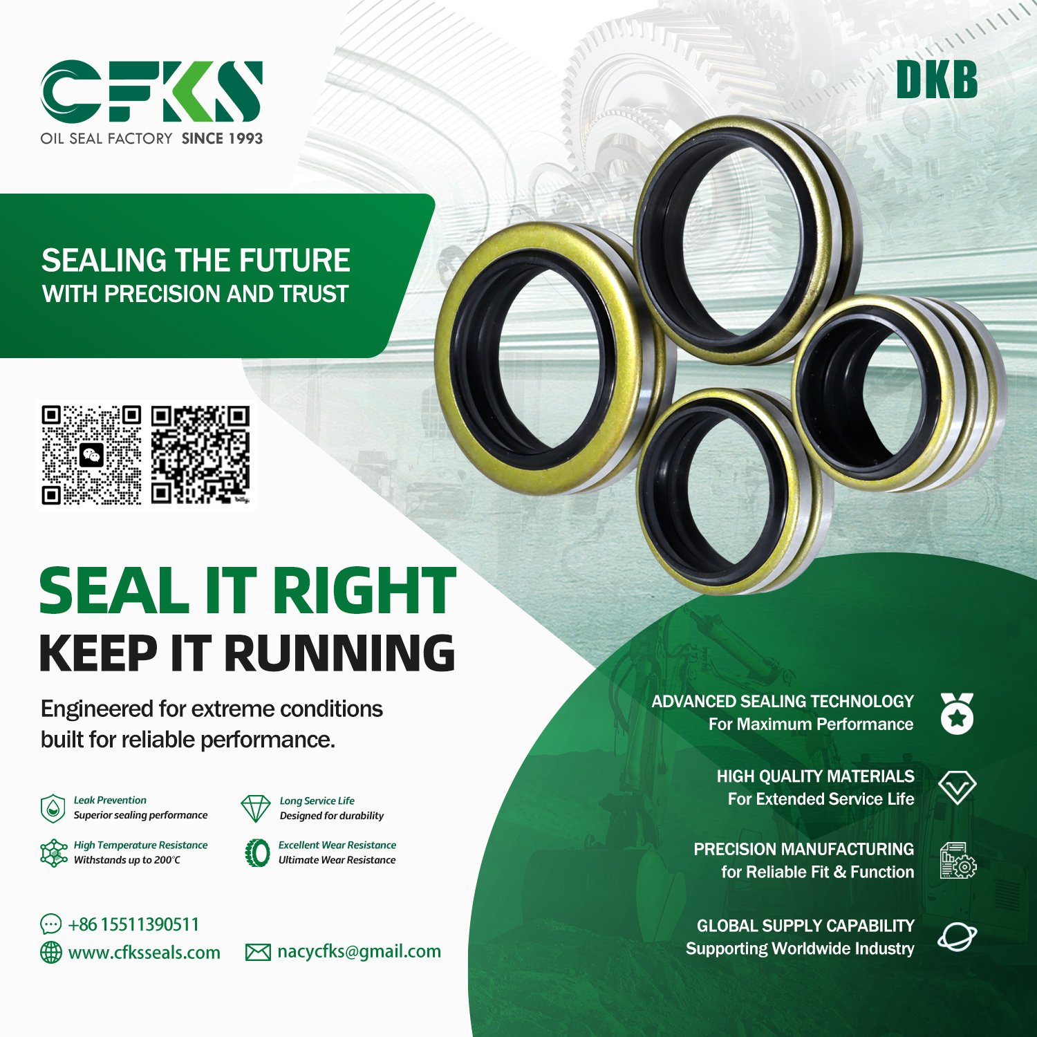
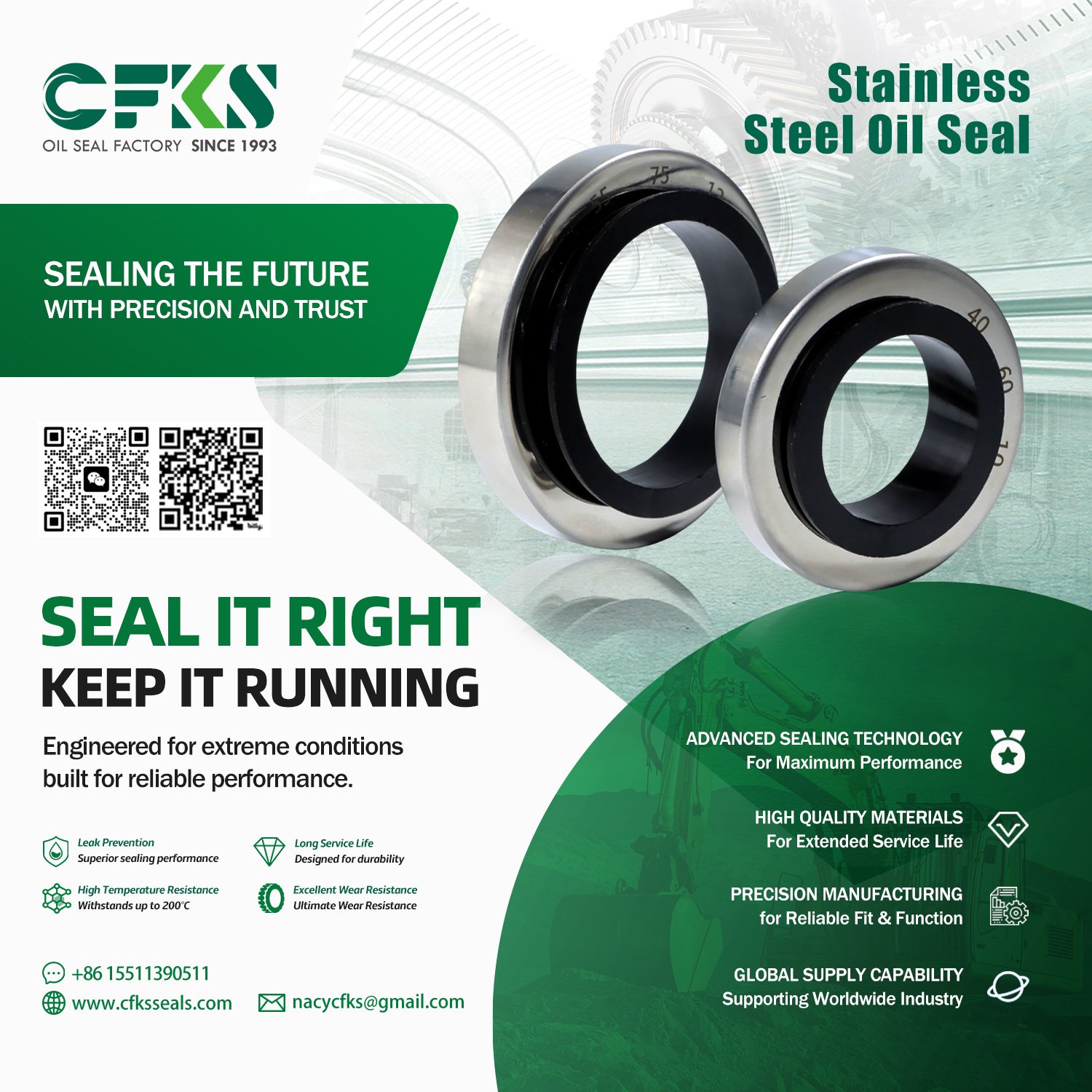
Rotary Shaft Oil Seal: A fluid-sealing component mounted in a housing bore around a rotating shaft to retain lubricants and exclude contaminants. Although both parts utilize engineered elastomers, a coupling spider is strictly a mechanical power transmission component, not a fluid seal.
Basic Structure of a Jaw Coupling Assembly
In a standard jaw coupling, each metal hub has precision-machined jaws arranged radially around its face. When the two hubs are brought together on the driving and driven shafts, their jaws alternate around the circumference. The elastomeric coupling spider sits between these alternating jaws so that torque is transferred purely through compression of the elastomer lobes rather than direct metal-to-metal contact.
3. Working Principles and Main Functions of a Coupling Spider
Torque Transmission
When the driving hub rotates, its metal jaws press directly against the alternating lobes of the coupling spider. These elastomer lobes compress against the jaws of the driven hub, transferring rotational force smoothly from the motor shaft to the driven machine shaft. In most standard jaw coupling designs, the elastomer operates primarily in compression, which offers higher load-carrying capacity than elastomer designs loaded strictly in shear.
Vibration Damping
Rotating machinery generates torsional vibrations caused by motor torque ripple, gear mesh frequencies, or pulsating pump and compressor loads. The viscoelastic nature of the elastomeric spider converts a portion of this vibrational energy into low-level internal heat, helping attenuate vibration before it amplifies across the drivetrain.
Shock Load Absorption
During heavy startups, sudden load changes, or conveyor jams, transient torque spikes occur. The flexible lobes of the coupling spider deform elastically under sudden compressive loads, cushioning the mechanical impact and reducing peak stress on gear teeth, keyways, and shafts.
Misalignment Accommodation
The elastomeric interface between the metal jaws permits limited angular (intersecting shaft axes), parallel/radial (offset shaft axes), and axial (end-float) misalignment. However, allowable misalignment is strictly bounded by the coupling size, rotational speed, torque load, and manufacturer specifications. Excessive misalignment accelerates elastomer wear and generates radial reaction forces on adjacent bearings.
Mechanical Overload Protection
In many jaw coupling designs, the elastomeric spider acts as a sacrificial mechanical element. If an extreme jam or severe overload occurs, the elastomer lobes are designed to shear or deform before catastrophic damage occurs to expensive motors, gearboxes, or driven shafts—allowing maintenance teams to restore operation by replacing only the insert.
4. Industrial Applications of Coupling Spiders
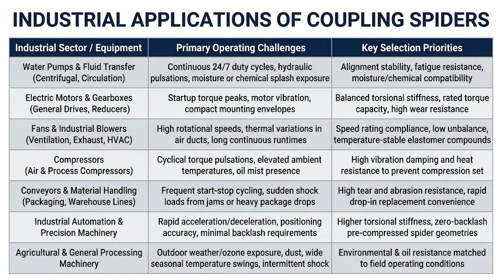
Coupling spiders are used across virtually every industrial sector that relies on motor-driven rotating equipment.
A. Water Pumps and Industrial Pump Systems
Centrifugal pumps, circulation pumps, booster skids, and water treatment equipment operate continuously for thousands of hours. Coupling spiders in pump drives dampen hydraulic pulsations and accommodate minor thermal growth between the motor and pump housing. Spacer-style jaw couplings are also widely used in process pumps so the elastomeric spider can be removed without disturbing pump or motor alignment.
B. Electric Motors and Gearboxes
General-purpose induction motors and variable-frequency drive (VFD) motors frequently connect to helical, worm, or planetary gearboxes via jaw couplings. The coupling spider cushions startup torque surges and isolates motor bearings from gearbox vibrations.
C. Fans and Blowers
Industrial ventilation systems, exhaust fans, and centrifugal blowers often run at high rotational speeds and experience elevated temperatures near process ductwork. Selecting a spider rated for the maximum operating RPM and ambient temperature prevents premature elastomer softening or centrifugal deformation.
D. Compressors
Reciprocating and rotary screw air compressors subject couplings to cyclic torque fluctuations and warm, oil-mist-laden enclosures. An oil-resistant, thermally stable spider helps prevent premature hardening and cracking under continuous pulsation.
E. Conveyors and Material Handling Equipment
Conveyor drives, packaging machinery, and warehouse sorting lines experience frequent start-stop cycles and unexpected shock loads when heavy loads drop onto belts or rollers. Tough, abrasion-resistant polyurethane spiders withstand repeated impact without rapid lobe wear.
F. Industrial Automation and Machinery
Automated assembly lines, machine tools, and mixing equipment require predictable torsional response. While standard jaw couplings prioritize vibration damping, precision servo-grade jaw couplings use pre-compressed, higher-hardness spiders to minimize torsional windup and backlash during rapid reversing cycles.
G. Agricultural and General Industrial Machinery
Irrigation pumps, grain handling equipment, and industrial mixers operate in dusty, outdoor environments with wide seasonal temperature variations and occasional oil or fuel exposure. Material selection must balance mechanical toughness with environmental and chemical resistance.
5. Coupling Spider Materials and Performance
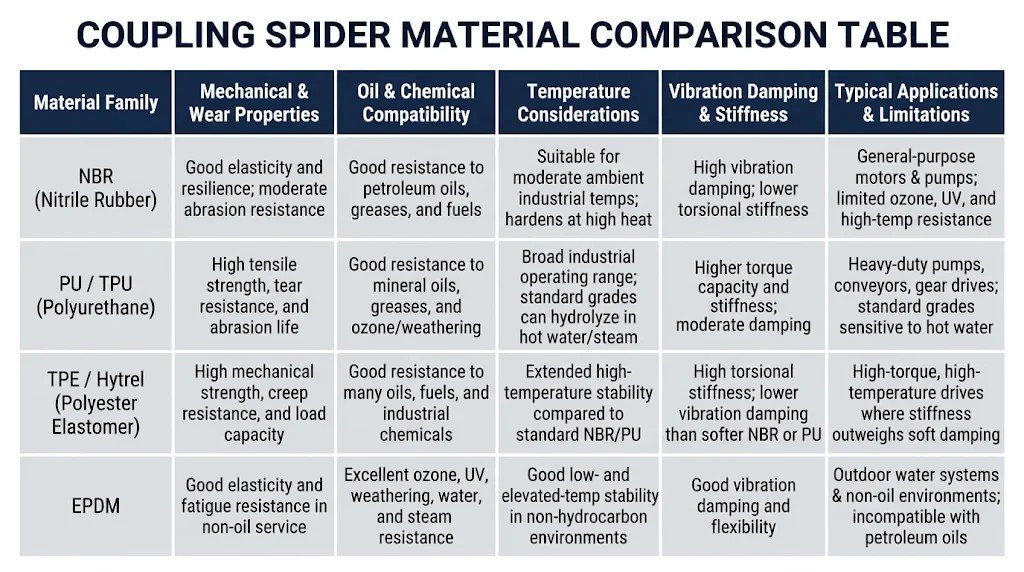
Coupling spiders are manufactured from several engineered elastomer families. Actual mechanical, thermal, and chemical performance depends on the specific polymer formulation, grade, hardness, and operating conditions rather than the base polymer name alone.
Key Material Selection Takeaways
-
NBR (Nitrile Butadiene Rubber): A common standard elastomer for general-purpose industrial jaw couplings. It provides strong vibration damping and reliable resistance to petroleum-based lubricants, though it offers lower torque capacity and abrasion resistance than polyurethane.
-
PU / TPU (Polyurethane / Thermoplastic Polyurethane): Widely selected for demanding industrial power transmission due to its high load-bearing strength, tear resistance, and long wear life under cyclic shock loads.
-
TPE / Polyester Elastomers: Engineered for higher torque transmission and elevated operating temperatures where higher torsional stiffness is needed, though their stiffer structure transmits more vibration than softer elastomers.
-
EPDM: Useful in outdoor, water, or polar-fluid environments requiring strong ozone and weather resistance, but must never be used where petroleum oils or greases are present due to severe chemical swelling.
6. Spider Hardness and Its Influence on Performance
Elastomer hardness—measured on the Shore A or Shore D durometer scale—governs how a coupling spider behaves under rotational load:
-
Lower-Hardness Spiders (e.g., softer Shore A grades):
-
Advantages: Provide greater elastic deformation, superior vibration damping, better shock load absorption, and slightly higher tolerance for minor shaft misalignment.
-
Trade-offs: Lower maximum torque rating, greater torsional windup (angular deflection under load), and higher heat buildup under high-frequency cyclic loads.
-
-
Higher-Hardness Spiders (e.g., firmer Shore A or Shore D grades):
-
Advantages: Support higher torque ratings within the same physical coupling envelope, deliver higher torsional stiffness, and improve positioning accuracy in automated machinery.
-
Trade-offs: Transmit more vibration and shock forces to connected bearings and impose higher reaction loads if shaft misalignment is present.
-
Engineering Principle: Higher hardness does not automatically mean better performance. Choosing an overly hard spider on a misaligned pump drive can overload motor bearings, whereas choosing an overly soft spider on a high-torque, reversing drive can cause rapid lobe deformation and overheating.
7. Different Coupling Spider Designs
Coupling spiders are manufactured in several structural configurations to match specific hub geometries and performance needs:
-
Standard Solid-Center Spiders: Feature a central elastomeric web connecting all lobes. While strong and easy to handle, the solid center prevents shafts from extending close together unless the coupling is spaced apart.
-
Open-Center (Ring-Type) Spiders: Feature a hollow center bore that allows shaft ends to protrude inside the coupling body, enabling shorter overall shaft-to-shaft distances in compact machinery.
-
Wrap-Around / Split Spiders: Designed with a radial split or wrap-around retaining ring so the spider can be installed or replaced radially without moving the driving or driven equipment.
-
Pre-Compressed Zero-Backlash Spiders: Used in precision motion control and servo couplings, where the elastomer lobes are slightly oversized relative to the hub jaw gaps so they sit under pre-compression, eliminating angular backlash.
-
Varying Lobe Counts and Profiles: Depending on coupling size and manufacturer design, spiders may feature 4, 6, 8, or more curved lobes with crowned or contoured faces to distribute compressive stress evenly during angular misalignment.
Important Compatibility Warning: Coupling spider dimensions, lobe counts, and tooth profiles are not universally standardized across all brands. Even if two spiders look visually similar or share the same color, subtle differences in lobe thickness, root radius, or pitch diameter can cause improper fit, uneven loading, or rapid failure. Always verify exact dimensional compatibility with the coupling hub model.
8. Common Coupling Spider Failure Causes
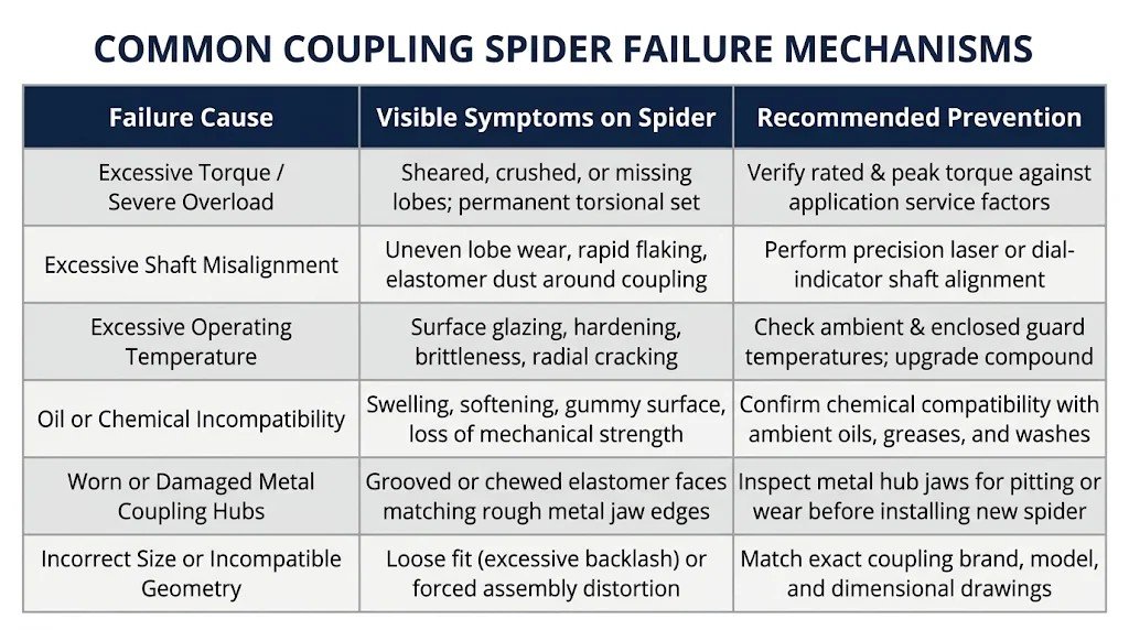
Regular visual and operational inspection helps identify coupling spider deterioration before total drivetrain loss occurs.
Warning Signs of Deterioration
Maintenance technicians should check for early indicators during routine inspections:
-
Surface cracks, crazing, or missing chunks on the elastomer lobes
-
Permanent flattening or thinning of the lobes (compression set)
-
Fine polymer powder or debris accumulating inside the coupling guard
-
Noticeable rotational play (backlash) when turning the coupling by hand
-
Increased vibration, knocking noises during startup/shutdown, or elevated coupling housing temperatures
9. How to Choose the Right Coupling Spider
Selecting a replacement or OEM coupling spider based solely on color or visual appearance is unreliable, as different manufacturers use different color-coding conventions for hardness and material. Use the following technical checklist:
-
Coupling Brand and Series Model: Identify the exact hub manufacturer and series (e.g., standard industrial jaw series vs. precision servo jaw series).
-
Exact Dimensional Geometry: Confirm outer diameter (OD), inner diameter (ID), overall thickness/width, lobe count, and lobe profile.
-
Rated and Peak Torque: Calculate nominal operating torque from motor power and speed, and apply an appropriate service factor for startup and shock loads.
-
Operating Speed (RPM): Verify that the spider and hub assembly are rated for the maximum rotational speed of the drive.
-
Shaft Alignment Condition: Confirm angular, parallel, and axial alignment tolerances during installation.
-
Operating Temperature Range: Account for both ambient plant temperature and localized heat buildup inside coupling guards.
-
Material Family and Shore Hardness: Balance vibration damping, torsional stiffness, and wear life for the specific load profile.
-
Environmental and Chemical Exposure: Check for exposure to lubricating oils, hydraulic fluids, water, cleaning agents, dust, and outdoor UV/ozone.
-
Duty Cycle and Maintenance Access: Consider continuous 24/7 operation versus intermittent cycling, and whether open-center or wrap-around designs simplify maintenance.
10. Installation, Inspection and Maintenance Best Practices
Proper installation extends coupling spider service life and protects connected equipment:
-
Inspect Coupling Hubs First: Clean both metal hubs and examine the jaw faces for burrs, wear grooves, or corrosion. Installing a new spider into worn metal jaws will rapidly destroy the new insert.
-
Verify Fit Without Excessive Force: The spider should slide smoothly between the metal jaws with light hand pressure. Never hammer a spider into misaligned hubs.
-
Check Shaft Gap (DBSE): Maintain the axial gap between hub faces specified by the coupling manufacturer so the spider is not pinched axially against the hub bodies.
-
Perform Precision Shaft Alignment: Align the driving and driven shafts using straightedges, dial indicators, or laser alignment tools according to the coupling manufacturer’s allowable limits.
-
Install Safety Guards and Schedule Inspections: Always secure rotating equipment guards before startup, and inspect the spider during scheduled maintenance windows based on actual operating severity.
11. 2026 Industry Outlook for Elastomeric Coupling Elements
Developments in industrial automation, motor technology, and asset management continue to shape how coupling spiders are specified and maintained:
-
Electrification and Variable-Speed Drives: Widespread adoption of high-efficiency electric motors and variable-frequency drives (VFDs) across pumps, fans, and automated lines requires couplings that handle broad speed ranges without exciting torsional resonance.
-
Engineered Polyurethane and Elastomer Formulations: Ongoing advancements in polyurethane and thermoplastic elastomer compounding focus on improving fatigue life, tear strength, and resistance to heat and industrial lubricants.
-
Maintainability and Reduced Unplanned Downtime: Industrial facilities increasingly favor modular drivetrain designs with easily replaceable elastomeric inserts so maintenance teams can restore equipment quickly without full shaft disassembly.
-
Condition Monitoring and Predictive Maintenance: Vibration sensors, thermography, and stroboscopic inspections allow maintenance engineers to detect increasing torsional backlash or elastomer heating early, scheduling spider replacements before sudden failure interrupts production.
-
Balancing Stiffness, Damping, and Energy Efficiency: In modern compact and precision machinery, engineers carefully match spider hardness and geometry to minimize parasitic vibration losses while maintaining accurate torque transfer.
12. Why Choose CFKS for Industrial Elastomer and Sealing Components?
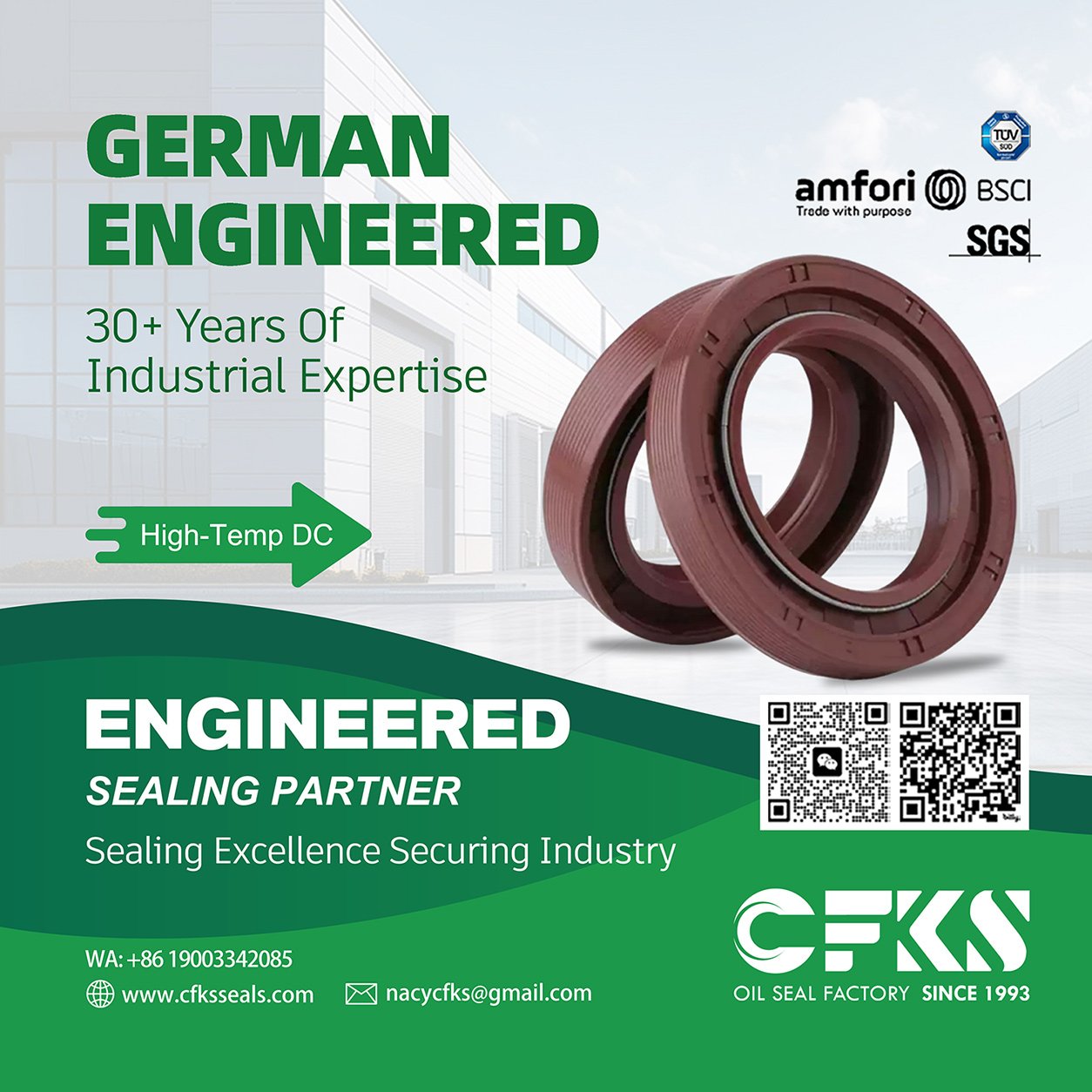
CFKS is an experienced manufacturer and international supplier specializing in industrial sealing products and precision elastomer components, guided by our brand commitment: Sealing Excellence Securing Industry. With factory-direct supply and export experience, CFKS supports equipment manufacturers, maintenance teams, and industrial distributors with dependable components tailored to real operating conditions.
When sourcing elastomer transmission inserts or industrial sealing products from CFKS, B2B buyers benefit from:
-
Customized Sizes and Material Options: Support for custom dimensions, elastomer formulations, hardness options, colors, and tailored packaging to match specific application requirements.
-
Quality Inspection and Product Consistency: Structured dimensional and visual quality checks to promote reliable fit and consistent batch performance.
-
Application-Oriented B2B Support: Direct communication with international buyers to review technical drawings, physical samples, and operating environments.
To inquire about coupling spiders, custom elastomer components, or industrial sealing solutions, contact the CFKS team:
-
Website: https://www.cfksseals.com
-
Email: cfksnacy@gmail.com
13. Conclusion
A Coupling Spider plays a vital role in protecting rotating industrial machinery by transmitting torque smoothly, damping torsional vibration, absorbing shock loads, and accommodating limited shaft misalignment. Because elastomeric inserts operate as replaceable mechanical wear components, achieving reliable long-term performance requires matching the exact spider geometry, material family, and Shore hardness to the actual torque, speed, alignment, and environmental conditions of the drive. For technical inquiries, sample evaluations, or customized elastomer component supply, reach out to CFKS at https://www.cfksseals.com or cfksnacy@gmail.com.
-
Share this article
Latest articles
November 20, 2026
November 20, 2026