O-Ring Kit: Applications, Components, Materials and Selection Guide for Industrial Sealing Systems
By CFKS SEALSPublished On: 2026-10-30
A. Introduction: Why O-Ring Kits Matter in Industrial Maintenance
In industrial processing plants, automated manufacturing cells, and fluid power installations, elastomeric O-rings serve as indispensable boundary seals. Engineered to prevent fluid or gas leakage across mating mechanical interfaces, these precision toroidal rings support the steady-state performance of hydraulic cylinders, directional control valves, process pumps, and pneumatic actuators.
Despite their compact cross-sections and seemingly simple geometries, O-rings operate under complex elastomeric mechanics. When an elastomeric seal deteriorates due to thermal degradation, chemical incompatibility, or mechanical over-compression, the resulting seal failure can prompt catastrophic fluid release. For industrial facilities, uncontained hydraulic or pneumatic leakage leads to dropped line pressure, environmental and occupational hazards, mechanical component seizure, and costly unplanned downtime.
+-----------------------------------------------------------------------------+
|                     TYPICAL DRIFT TOWARD SEAL FAILURE                       |
|                                                                             |
|  [ Improper Seal Sizing ]                                                   |
|           │                                                                 |
|           ▼                                                                 |
|  [ Excessive Gap Extrusion / Chemical Swell ]                               |
|           │                                                                 |
|           ▼                                                                 |
|  [ Micro-Fissuring & Nibbling ]                                             |
|           │                                                                 |
|           ▼                                                                 |
|  [ Hydrodynamic Boundary Breach ] ──> Unplanned Line Stoppage & Fluid Loss   |
+-----------------------------------------------------------------------------+
An O-Ring Kit serves as a vital safeguard against extended operational disruptions. Rather than maintaining disorganized loose bins or attempting emergency retrofits with mismatched seals, maintenance engineers rely on structured O-Ring Kits to source verified, dimensionally accurate replacements.
However, an O-ring kit provides genuine mechanical reliability only when configured according to the exact engineering demands of the target equipment. Selecting an effective kit requires matching inner diameters (ID), cross-sectional thicknesses (CS), elastomer base polymers, durometer hardness, and fluid compatibility to the intended operational envelope.
B. What Is an O-Ring Kit?
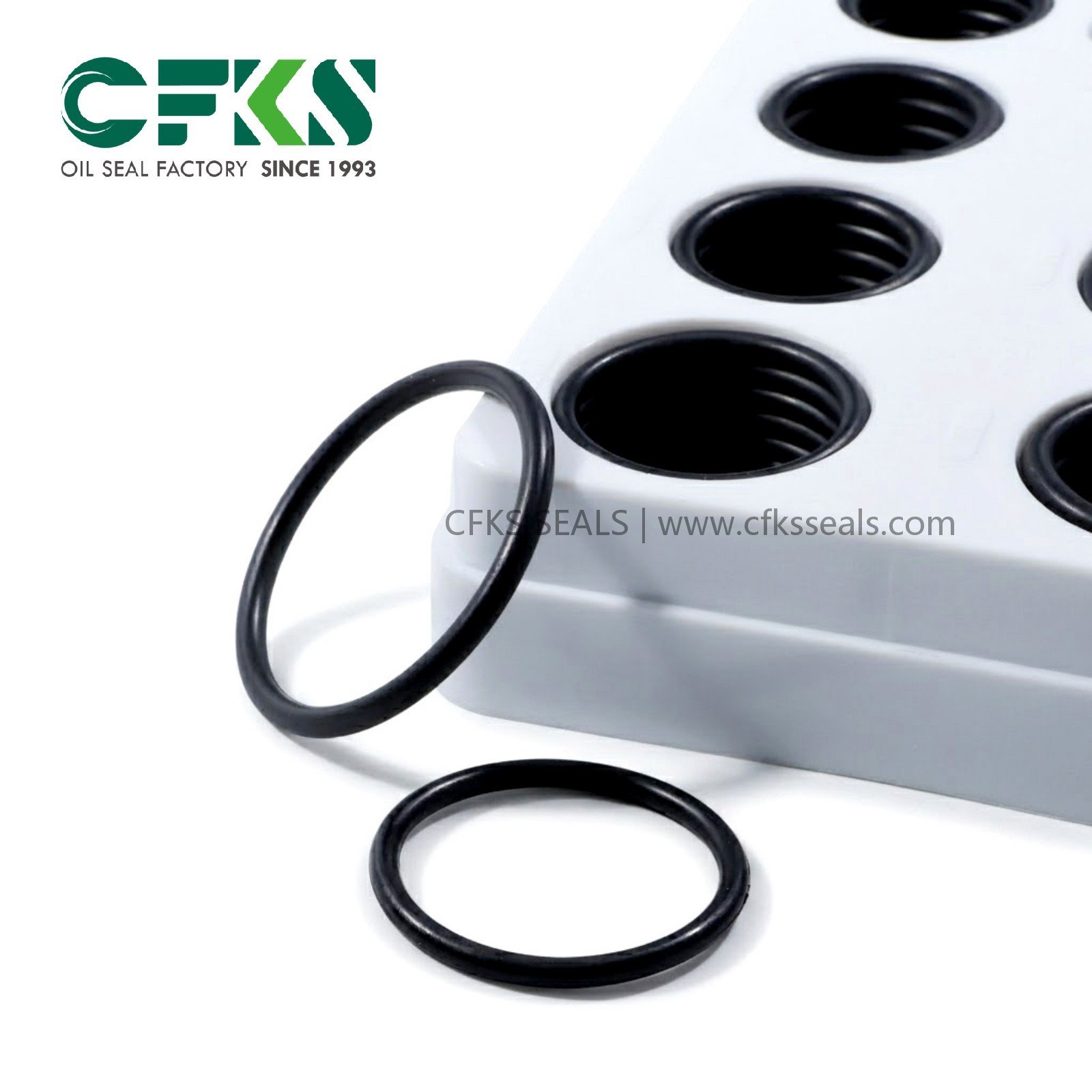
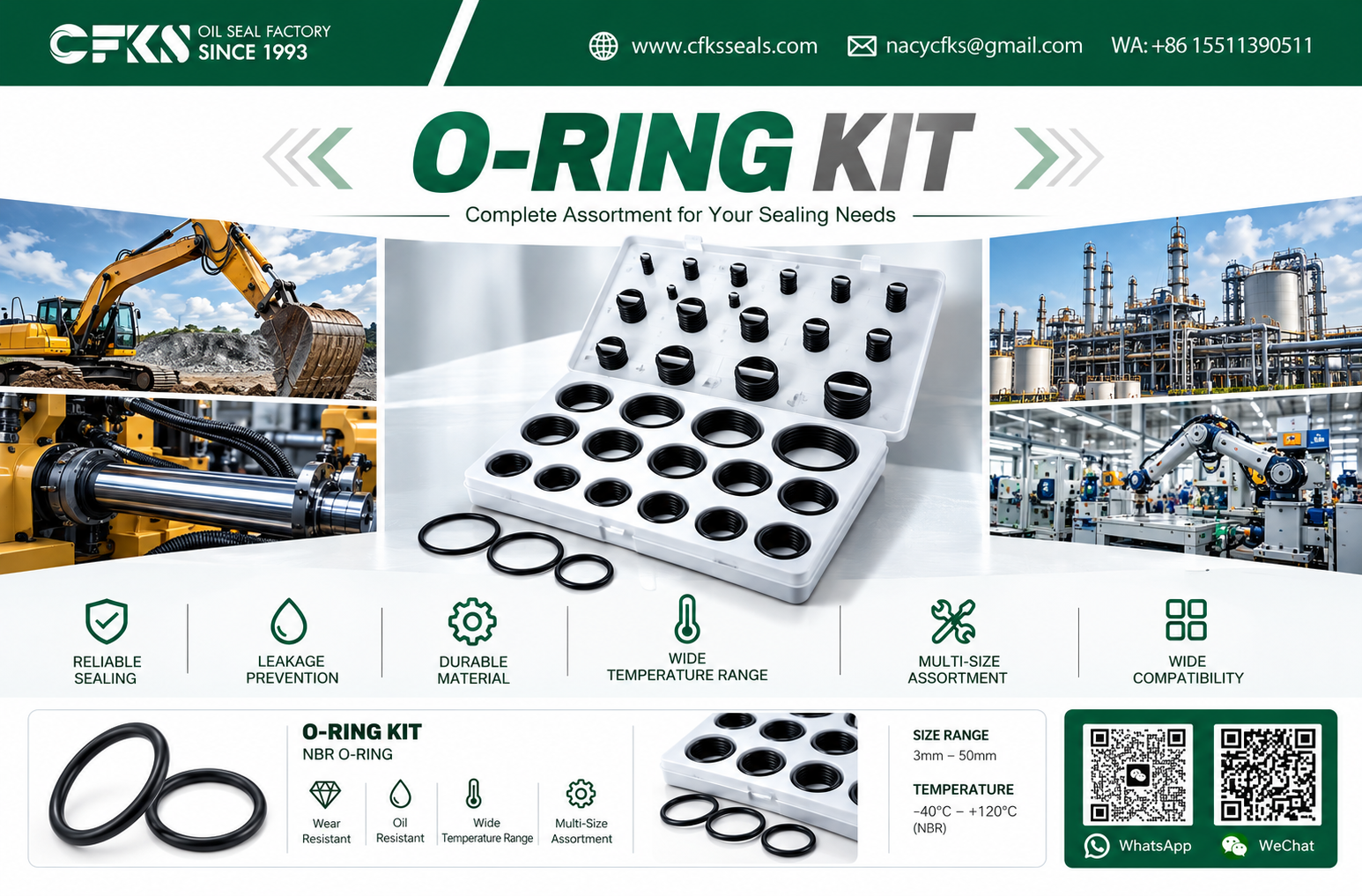
An O-Ring Kit is an organized, compartmentalized industrial enclosure containing an assortment of precision elastomeric O-rings arranged systematically by internal diameter and cross-section. The composition of these kits is not universal; configurations vary widely depending on industrial sizing standards, equipment duty ratings, and targeted application sectors.
+-----------------------------------------------------------------------------+
|                          PRIMARY O-RING KIT CLASSES                         |
+-----------------------------------+-----------------------------------------+
| Kit Classification                | Primary Engineering Target              |
+-----------------------------------+-----------------------------------------+
| General Industrial Kits           | Broad plant maintenance; covers common  |
|                                   | static flanges and low-pressure unions. |
+-----------------------------------+-----------------------------------------+
| Hydraulic O-Ring Kits             | High-pressure circuits; features high-  |
|                                   | durometer elastomers & backup rings.    |
+-----------------------------------+-----------------------------------------+
| Pneumatic O-Ring Kits             | Low-friction dynamic air systems;       |
|                                   | prioritizes wear and tear resistance.   |
+-----------------------------------+-----------------------------------------+
| Equipment-Specific Service Kits   | Pre-matched to specific pump, valve, or |
|                                   | cylinder models for complete rebuilds.  |
+-----------------------------------+-----------------------------------------+
| Metric / Imperial Assortments     | Standardized to ISO 3601 or AS568       |
|                                   | dimensional matrices.                   |
+-----------------------------------+-----------------------------------------+
General-Purpose Assortments vs. Application-Specific Kits
-
General-Purpose Assortment Kits: Typically populated with broad geometric spreads compliant with standard sizing frameworks (such as AS568 in North America or ISO 3601 metric series globally). These provide rapid, first-response capability across generic factory maintenance environments.
-
Application-Specific & Customized Kits: Tailored to dedicated machine footprints—such as high-pressure proportional valves or chemical metering pumps. Rather than spanning hundreds of disparate sizes, these kits curate the exact internal dimensions, specialized durometers (e.g., 90 Shore A for anti-extrusion), and matching back-up elements required to execute a complete, reliable machine rebuild.
C. Components and Configurations in an Industrial O-Ring Kit
Industrial O-ring kits can include diverse components designed to facilitate effective maintenance and prevent repeated failure:
+-----------------------------------------------------------------------------+
|                   ANATOMY OF AN ADVANCED INDUSTRIAL KIT                     |
|                                                                             |
|  ┌───────────────────┬───────────────────┬───────────────────┐              |
|  │  O-Rings (70 ShA) │  O-Rings (90 ShA) │ PTFE Backup Rings │              |
|  │  Primary Sealing  │  Pressure Ports   │ Anti-Extrusion    │              |
|  ├───────────────────┴───────────────────┴───────────────────┤              |
|  │            High-Contrast Calibrated Sizing Gauge          │              |
|  ├───────────────────────────────────────────────────────────┤              |
|  │      Elastomer-Compatible Boundary Installation Lubricant │              |
|  ├───────────────────────────────────────────────────────────┤              |
|  │      Rugged Case with Chemical-Resistant Spec Labeling    │              |
|  └───────────────────────────────────────────────────────────┘              |
+-----------------------------------------------------------------------------+
-
Dimensional Assortments: Precision O-rings partitioned by ascending internal diameters across standard cross-sectional steps (e.g., 1.78 mm, 2.62 mm, 3.53 mm, 5.33 mm, and 6.99 mm for imperial series; or standardized metric steps).
-
Elastomeric Base Polymers: Single-compound kits (e.g., standard NBR) or dual-material layouts (e.g., pairing NBR with high-temperature FKM) to support diverse chemical lines.
-
Durometer Variations: Combining standard 70 Shore A seals with 90 Shore A variants designed specifically for elevated hydraulic pressures.
-
Anti-Extrusion Backup Rings: Solid, spiral, or scarf-cut virgin or filled PTFE backup rings configured to fit standard gland widths alongside elastomeric O-rings.
-
Specialized Sealing Rings: Selected kits incorporate X-rings (quad-rings) for reciprocating dynamic rods or square-cut rings for high-stress static flanges.
-
Installation Accessories: Ergonomic, non-scratch extraction picks (brass or reinforced polymer) to prevent gland scoring, alongside elastomeric assembly lubricants formulated to reduce boundary friction during installation.
-
Identification Matrices: High-contrast case labels outlining nominal dimensions, standard dash numbers (e.g., AS568 or ISO 3601 codes), material designations, durometer ratings, and production batch identifiers.
D. Working Principles of Elastomeric O-Rings
The O-ring functions on the principle of controlled elastic deformation within a precision-machined gland. Its operating envelope can be separated into two mechanical stages: initial mechanical pre-compression and system pressure energization.
   STATIC AT REST (PRE-COMPRESSION)             SYSTEM PRESSURE APPLIED

        Housing Gland Wall                           Housing Gland Wall
      ┌───────────────────────┐                    ┌───────────────────────┐
      │       Fluid Void      │                    │ Fluid  │              │
      │         │             │                    │ Press. │   Deformed   │
      │         ▼             │                    │ ======►│    Elastomer │
      │      ┌─────┐          │                    │ ======►│    Flowing   │
      │     │       │         │                    │ ======►│   Into Void  │
      │      └─────┘          │                    │        │              │
      └───────────────────────┘                    └───────────────────────┘
      =========================                    =========================
             Mating Surface                               Mating Surface
Initial Mechanical Pre-Compression
When installed in an engineered groove, the O-ring experiences an initial mechanical squeeze—typically between 15% and 30% of its free cross-sectional diameter in static assemblies, and between 8% and 20% in dynamic interfaces. This physical interference produces initial contact stress against both the internal groove base and the mating face, forming a zero-pressure hermetic seal.
System Pressure Energization
As system pressure mounts, the fluid displaces the elastomeric ring toward the low-pressure side of the cavity. Because elastomers behave as incompressible, highly viscous fluids with high Poisson’s ratios (approaching 0.5), applied hydraulic or pneumatic pressure transmits through the cross-section.
The contact stress between the elastomer and the sealing faces increases proportionally with the applied fluid pressure, maintaining a continuous barrier against leakage.
Boundary Geometries: Static vs. Dynamic
-
Static Sealing: The mating metal components experience no relative motion.
-
Axial Assemblies: Squeeze is applied parallel to the ring’s centerline (e.g., pipe flanges, cylinder end caps).
-
Radial Assemblies: Squeeze is applied perpendicular to the ring’s centerline (e.g., plug-in connections, valve manifolds).
-
-
Dynamic Sealing: The mating surfaces execute relative motion against the elastomeric boundary.
-
Reciprocating: Linear shaft and piston travel in hydraulic and pneumatic cylinders.
-
Rotary: Low-speed rotating or oscillating shafts, which require careful friction management to prevent localized thermal degradation.
-
Critical Gland Geometries
+─────────────────────────────────────────────────────────────────────────────+
|                         CRITICAL GLAND PARAMETERS                           |
|                                                                             |
|      ◄───────────── Gland Width (W) ─────────────►                          |
|     ┌─────────────────────────────────────────────┐                         |
|     │                                             │                         |
|     │      ▲                                      │                         |
|     │      │                                      │                         |
|     │  Gland Depth (D)                            │                         |
|     │      │                                      │                         |
|     │      ▼                                      │                         |
|     └─────────────────────────────────────────────┘  ▲                      |
|     ═══════════════════════════════════════════════  │ Diametral Clearance  |
|                     Mating Component                 ▼                      |
+─────────────────────────────────────────────────────────────────────────────+
-
Squeeze: The percentage reduction of the original cross-section. Insufficient squeeze causes low-pressure weeping; excessive squeeze accelerates micro-cracking and assembly damage.
-
Gland Volume & Stretch: Grooves must accommodate thermal expansion and chemical swell. O-ring cross-sectional area should typically occupy no more than 75% to 85% of the total gland volume. Installed inner-diameter stretch should generally remain below 2% to 5% to prevent cross-sectional thinning.
-
Extrusion Clearance Gap: The diametral gap on the low-pressure side of the gland. Under high pressures, the elastomer can be forced into this micro-gap, causing physical nibbling and destruction unless restrained by backup rings.
E. Industrial Applications of O-Ring Kits
1. Hydraulic Systems and Fluid Power
Hydraulic installations operate under severe cyclic loading, continuous fluid shear, and elevated system pressures (often exceeding 16 to 35 MPa). O-ring kits designed for hydraulics must feature high-modulus, high-durometer compounds (e.g., 85–90 Shore A NBR or FKM).
        TYPICAL HYDRAULIC CYLINDER HEAD SEAT GLAND

   Cylinder Barrel
 ┌──────────────────────────────────────────────────────────────┐
 │                                                              │
 │             Gland Void                                       │
 │           ┌───────────┬──────────────┐                       │
 │           │   PTFE    │  Elastomeric │                       │
 │           │  Backup   │    O-Ring    │                       │
 │           │   Ring    │   (90 ShA)   │                       │
 │           └───────────┴──────────────┘                       │
 └──────────────────────────────────────────────────────────────┘
 ================================================================
   Piston Rod Surface (Reciprocating Dynamic Motion)
Within hydraulic directional control valves, subplate manifolds, and hydrostatic pump casings, O-rings provide primary fluid boundaries. When high pressure spikes occur, backup rings prevent the elastomer from extruding through the diametral clearance gaps.
2. Industrial Pneumatics and Automation
Pneumatic cylinders, air preparation units (FRL assemblies), and solenoid piloting valves operate under different tribological conditions. Unlubricated or minimally lubricated compressed air circuits can accelerate abrasive wear on elastomeric contact faces.
Kits for pneumatic service prioritize lower-durometer compounds (typically 70 Shore A) with reduced friction coefficients, helping to limit breakaway drag and prevent premature wear during high-cycle automated operations.
3. Industrial Pumps and Process Valves
Centrifugal process pumps, high-pressure slurry feeds, chemical metering pumps, and industrial gate/ball valves rely on O-rings to seal internal housings, mechanical seal glands, and pipe connection points.
These interfaces frequently face aggressive media, fluctuating temperatures, cavitation, and fluid-induced vibration. Maintenance teams must have rapid access to high-grade FKM or chemically inert elastomers to service pump casings without risking early seal degradation.
+-----------------------------------------------------------------------------+
|                     SEALING REQUIREMENTS BY INDUSTRIAL SECTOR               |
+----------------------+--------------------+---------------------------------+
| System Class         | Dominant Pressures | Critical Sealing Challenges     |
+----------------------+--------------------+---------------------------------+
| Hydraulic Power      | 10 to 40+ MPa      | Extrusion, hydraulic fluid      |
| Units (HPUs)         |                    | compatibility, pressure spikes. |
+----------------------+--------------------+---------------------------------+
| Pneumatic Logic      | 0.4 to 1.0 MPa     | Dynamic friction, dry-air wear, |
| & Actuators          |                    | fast cycle response.            |
+----------------------+--------------------+---------------------------------+
| Chemical & Process   | 0.2 to 5.0 MPa     | Chemical degradation, thermal   |
| Pumping Units        |                    | excursions, cavitation cycles.  |
+----------------------+--------------------+---------------------------------+
| Heavy Automated      | 5 to 25 MPa        | Continuous 24/7 cycling, rapid  |
| Machinery Lines      |                    | shock loading, vibration.       |
+----------------------+--------------------+---------------------------------+
| Marine Deck Machinery| 10 to 25 MPa       | Salt mist corrosion, UV exposure|
| & Fluid Transfer     |                    | ambient moisture, mineral oils. |
+----------------------+--------------------+---------------------------------+
4. Marine and Industrial Offshore Equipment
Deck-mounted winches, cargo handling gear, ballast control actuators, and auxiliary hydraulic drives in marine settings operate in punishing, salt-laden environments. The O-rings in these systems must withstand environmental UV and ozone, salt mist, and petroleum-based fluids.
Using standard, unverified elastomer formulations in these harsh settings can accelerate thermal-oxidative degradation, requiring specialized materials matched to the operating environment.
F. O-Ring Materials: Selecting the Right Elastomeric Compound
Selecting an O-ring kit requires a careful assessment of compound chemistry. Operating an elastomer outside its compatible fluid or thermal envelope will rapidly compromise its sealing integrity.
+------------------------------------------------------------------------------------------------------+
|                               ELASTOMERIC MATERIAL COMPARISON MATRIX                                 |
+-----------+--------------------+-------------------------+--------------------+----------------------+
| Polymer   | ASTM D1418         | Typical Working         | Primary Chemical   | Incompatibilities &  |
| Family    | Designation        | Temperature Envelope*   | Compatibility      | Operational Limits   |
+-----------+--------------------+-------------------------+--------------------+----------------------+
| Nitrile   | NBR                | -30°C to +100°C         | Mineral-based oils,| Ozone, weathering,   |
| Butadiene |                    | (Specialty formulations | petroleum fluids,  | automotive brake     |
| Rubber    |                    | to -40°C or +120°C)     | water, glycols.    | fluids, ketones.     |
+-----------+--------------------+-------------------------+--------------------+----------------------+
| Fluoro-   | FKM                | -15°C to +200°C         | Synthetic esters,  | Low molecular weight |
| elastomer | (e.g., Viton®)     | (Specialty cold-grades  | aggressive fuels,  | organic acids, steam,|
|           |                    | down to -40°C)          | acids, aromatics.  | amines, Skydrol®.    |
+-----------+--------------------+-------------------------+--------------------+----------------------+
| Ethylene  | EPDM               | -45°C to +130°C         | Hot water, steam,  | Petroleum oils,      |
| Propylene |                    | (Steam formulations     | brake fluids,      | mineral greases,     |
| Diene     |                    | up to +150°C)           | polar solvents.    | hydrocarbons.        |
+-----------+--------------------+-------------------------+--------------------+----------------------+
| Silicone  | VMQ                | -60°C to +200°C         | High/low temp air, | Dynamic friction,    |
| Rubber    |                    | (Intermittent peaks     | engine oils, ozone,| shear loading,       |
|           |                    | up to +230°C)           | weathering.        | concentrated acids.  |
+-----------+--------------------+-------------------------+--------------------+----------------------+
| Hydro-    | HNBR               | -30°C to +150°C         | Refined oils, sour | Polar solvents,      |
| genated   |                    | (Improved mechanical    | gas (H2S), cutting | strong acids,        |
| Nitrile   |                    | strength over NBR)      | fluids, coolants.  | chlorinated agents.  |
+-----------+--------------------+-------------------------+--------------------+----------------------+
| Poly-     | PTFE               | -200°C to +250°C        | Universal chemical | Poor recovery/memory;|
| tetra-    | (Backup Rings)     | (Near universal thermal | inertness, zero    | susceptible to cold  |
| fluoro-   |                    | envelope)               | swell in solvents. | flow under load.     |
| ethylene  |                    |                         |                    |                      |
+-----------+--------------------+-------------------------+--------------------+----------------------+
*Note: Temperature spans depend strictly on specific compounding formulations, plasticizer packages, cure systems, and manufacturer test standards. Consult precise compound data sheets before final specification.
Technical Distinctions Between Primary Compounds
Nitrile Butadiene Rubber (NBR)
The workhorse of industrial hydraulics and pneumatics. NBR is a copolymer of butadiene and acrylonitrile (ACN). Formulations with higher ACN content offer improved resistance to petroleum-based oils and hydrocarbon fuels, but show reduced low-temperature elasticity.
NBR exhibits good abrasion resistance and mechanical shear properties, making it an ideal choice for standard industrial fluid power applications. However, it offers limited resistance to atmospheric ozone, UV radiation, and polar fluids.
Fluoroelastomer (FKM)
FKM compounds feature fluorinated polymer chains that provide exceptional resistance to high temperatures, oxidation, synthetic lubricants, fuels, and aggressive chemical reagents.
It is the standard choice for severe-duty industrial plant applications where internal bulk oil temperatures exceed 100°C, or where synthetic fire-resistant fluids (such as HFD-R phosphate esters) would degrade standard NBR.
However, standard FKM compounds exhibit reduced elasticity at temperatures below -15°C, requiring specialized low-temperature grades for cold-weather operations.
Ethylene Propylene Diene Monomer (EPDM)
Synthesized from ethylene, propylene, and a diene monomer, EPDM provides dependable sealing performance across hot water, low-pressure steam, and polar solvent lines (e.g., ketones, alcohols). It is also highly resistant to environmental weathering, ozone, and UV exposure.
Critical Operational Warning: EPDM degrades rapidly when exposed to non-polar hydrocarbons, petroleum-based oils, fuels, or mineral greases. Introducing an EPDM seal into a standard petroleum hydraulic loop will cause rapid, destructive chemical swelling and catastrophic joint failure within hours.
       CHEMICAL VOLUMETRIC SWELL COMPARISON OVER TIME

  Volume Swell (%)
       ▲
   60% ┼─────────────────────────────── EPDM in Petroleum Oil (Rapid Swell & Rupture)
       │
   40% ┼
       │
   20% ┼
       │
    0% ┼─────────────────────────────── NBR in Petroleum Oil (Controlled Stabilization)
       └─────────────────────────────► Exposure Time (Hours)
Silicone Rubber (VMQ)
Characterized by a flexible silicon-oxygen backbone, VMQ maintains its elastic properties across wide temperature extremes (from -60°C up to +200°C).
However, VMQ exhibits relatively low tensile strength, poor tear resistance, and high dynamic friction coefficients. Consequently, its industrial use is generally limited to static interfaces, food/beverage processing equipment, and low-friction thermal enclosures, rather than dynamic fluid power shafts.
Hydrogenated Nitrile (HNBR)
Produced via the controlled selective hydrogenation of the butadiene subunits in NBR, HNBR provides significantly higher mechanical tensile strength, greater tear resistance, and lower compression set than standard nitrile compounds.
It resists continuous operating temperatures up to 150°C and withstands modern industrial oils with aggressive additive packages, making it an excellent bridge between standard NBR and premium FKM.
PTFE (Polytetrafluoroethylene) Backup Rings
Virgin or bronze/carbon-filled PTFE backup rings are non-elastomeric elements used to reinforce elastomeric O-rings against high pressures. Positioned on the low-pressure side of an O-ring groove, a PTFE backup ring bridges the clearance gap, preventing the pressurized elastomeric O-ring from extruding under heavy dynamic loads.
G. Strategic Comparison: O-Ring Kit vs. Individual O-Ring Procurement
Procurement managers and maintenance leads often weigh the cost-efficiency of purchasing bulk individual O-rings against deploying standardized O-Ring Kits across operational lines.
+------------------------------------------------------------------------------------------------------+
|                           O-RING KIT VS. INDIVIDUAL O-RING SOURCING                                  |
+----------------------+---------------------------------------+---------------------------------------+
| Comparison Vector    | Pre-Configured / Custom O-Ring Kits   | Bulk Individual O-Ring Purchasing     |
+----------------------+---------------------------------------+---------------------------------------+
| Immediate Component  | Instantaneous; verified sizes are     | Dependent on stockroom staging; risk  |
| Availability         | directly on-hand for line technicians.| of out-of-stock sizes on rare lines.  |
+----------------------+---------------------------------------+---------------------------------------+
| Line Diagnostic      | High; allows rapid dynamic trial of   | Low; requires manual parts lookup and |
| Convenience          | adjacent cross-sections if needed.    | single-part inventory requests.       |
+----------------------+---------------------------------------+---------------------------------------+
| Inventory Complexity | Minimized; manages one master SKU     | High overhead; tracks dozens of       |
| & Stock Overhead     | for multiple physical component sizes.| separate parts and bins.              |
+----------------------+---------------------------------------+---------------------------------------+
| Error Minimization   | High; compartments feature stamped    | Moderate; loose storage bins risk     |
| During Assembly      | profiles and nominal specs.           | manual cross-contamination of sizes.  |
+----------------------+---------------------------------------+---------------------------------------+
| Sourcing Cost        | Higher initial acquisition price      | Lower per-unit component price        |
| Dynamics             | per individual seal.                  | when buying single sizes in bulk.     |
+----------------------+---------------------------------------+---------------------------------------+
| Strategic Plant      | Maintenance, emergency repair units,  | High-volume OEM serial manufacturing; |
| Suitability          | field service kits, valve overhauls.  | dedicated, fixed-dimension assembly.  |
+----------------------+---------------------------------------+---------------------------------------+
H. Common O-Ring Failure Modes: Root Causes and Prevention
Replacing an O-ring without identifying the underlying mechanical or chemical cause of its failure usually results in repeated maintenance issues.
+------------------------------------------------------------------------------------------------------+
|                              O-RING FAILURE ANALYSIS AND MITIGATION                                  |
+------------------+-----------------------------+---------------------------+-------------------------+
| Failure Mode     | Visual Symptoms             | Underlying Root Causes    | Preventive Engineering  |
|                  |                             |                           | Actions                 |
+------------------+-----------------------------+---------------------------+-------------------------+
| Compression Set  | Permanent flattening of the | Excessive operating heat; | Use high-spec compound; |
|                  | cross-section; loss of      | incompatible elastomer;   | verify gland depth;     |
|                  | original circular memory.   | excessive squeeze limits. | control sump operating  |
|                  |                             |                           | temperatures.           |
+------------------+-----------------------------+---------------------------+-------------------------+
| Extrusion and    | Ragged, frayed edges on the | Excessive fluid pressure; | Install PTFE backup     |
| Nibbling         | low-pressure side of the    | oversized clearance gap;  | rings; reduce gap;      |
|                  | seal; "chewed" appearance.  | durometer is too low.     | upgrade to 90 ShA.      |
+------------------+-----------------------------+---------------------------+-------------------------+
| Abrasive Wear    | Flattened surface finish    | Rough gland or rod finish;| Improve rod chrome;     |
|                  | along dynamic contact zone; | unlubricated compressed   | introduce system fluid  |
|                  | particulate generation.     | air; fluid contamination. | filtration (<10 µm).    |
+------------------+-----------------------------+---------------------------+-------------------------+
| Chemical Swell   | Significant volume growth;  | Fluid-elastomer chemical  | Verify compound compatibility;|
| & Softening      | loss of tensile strength;   | mismatch (e.g., EPDM in   | analyze additive packages;|
|                  | spongy, gummy texture.      | petroleum oils).          | swap to FKM or FFKM.    |
+------------------+-----------------------------+---------------------------+-------------------------+
| Thermal Aging    | Surface micro-cracks,       | Sustained temperatures    | Upgrade compound class; |
| & Hardening      | hardening, brittleness;     | exceeding the polymer's   | improve heat dissipation|
|                  | fractures upon bending.     | thermal ceiling.          | around valve bodies.    |
+------------------+-----------------------------+---------------------------+-------------------------+
| Installation     | Clean, sharp cuts; notched  | Sharp edges on ports,     | Deburr internal bores;  |
| Damage (Slicing) | circumference; spiral       | threads, or keyways;      | use installation sleeves|
|                  | splitting along the body.   | zero assembly lube.       | and chamfer transitions.|
+------------------+-----------------------------+---------------------------+-------------------------+
| Spiral Failure   | Deep 45-degree rotational   | Reciprocating stroke on   | Increase durometer;     |
|                  | cracks along the body;      | long strokes; uneven      | swap to X-Rings; verify |
|                  | twisted cross-section.      | lubrication; oval glands. | dynamic concentricity.  |
+------------------+-----------------------------+---------------------------+-------------------------+
     EXTRUSION / NIBBLING DETAIL

     High Pressure Fluid
           │
           ▼
     ┌───────────┐    Clearance Gap
     │ Elastomer ├──┐  ▲
     │  Forced   │  │  │   Damaged/Extruded
     │   Down    │  ▼  ▼   "Nibbled" Flakes
     └───────────┴──▒▒▒▒ ◄─┘
     ═══════════════════════════════════
I. Engineering Checklist: How to Select the Right O-Ring Kit
Selecting an O-ring kit based on approximate physical dimensions alone is a common cause of premature seal failure in industrial plants. Maintenance teams should evaluate each of the following engineering parameters:
[ ] 1. Sizing Matrix Verification
       └── Confirm standard: AS568 (Imperial) vs. ISO 3601 (Metric) vs. JIS B 2401.
       └── Ensure metric-to-inch conversions are not loosely rounded.

[ ] 2. Cross-Sectional & Internal Diameter Tolerances
       └── Measure using calibrated non-contact optical comparators or O-ring step cones.
       └── Cross-reference against ISO 3601-1 Class A (tight tolerance) or Class B.

[ ] 3. Base Fluid Compatibility
       └── Identify base oil: Mineral oil, synthetic ester, water-glycol (HFC), or Skydrol.
       └── Check compatibility with industrial cleaning agents and system flushes.

[ ] 4. Thermal Operational Envelope
       └── Minimum startup temperature (cold room vs. outdoor winter environments).
       └── Continuous bulk operating temperature and local thermal spikes.

[ ] 5. Pressure Class & Mechanical Load
       └── Is continuous system pressure ≤ 10 MPa (1,450 psi)?
       └── If > 10 MPa, are 90 Shore A rings or matching PTFE backup rings included?

[ ] 6. Dynamic vs. Static Gland Configuration
       └── Reciprocating rods or rotary shafts require lower initial squeeze.
       └── Purely static interfaces require higher squeeze to ensure a bubble-tight seal.

[ ] 7. Gland Dimension Compatibility
       └── Verify groove width, depth, and corner radii to prevent overfilling.
       └── Check that the clearance gap does not exceed allowable extrusion limits.

[ ] 8. Mechanical Hardness (Durometer)
       └── Standard low-pressure: 70 Shore A.
       └── High-pressure or pulsed circuits: 85 to 90 Shore A.
Dimensional Standards: Navigating ISO 3601, AS568, and Beyond
Engineers must recognize that the North American AS568 standard and the international ISO 3601 metric system organize dimensions differently. AS568 assigns fixed dash numbers to specific combinations of internal diameter and cross-section (e.g., Dash -214 denotes $0.984\text{ in ID} \times 0.139\text{ in CS}$).
Conversely, ISO 3601-1 categorizes metric O-rings using direct millimeter dimensions ($d_1 \times d_2$) across designated size codes. It also sets rigorous visual quality acceptance criteria (ISO 3601-3), limiting permissible flash, parting lines, and surface defects to Grade N (general purpose) or Grade S (special performance).
Standardizing your plant on verified, standard-compliant O-ring kits helps eliminate costly mismatch errors during emergency maintenance calls.
J. Storage, Shelf Life, and Maintenance Management
Elastomeric compounds are susceptible to environmental degradation over time if stored improperly. An unmanaged O-ring kit stored in direct sunlight or exposed to motor ozone can degrade before it is ever installed.
       OPTIMAL O-RING PRESERVATION CONDITIONS
  +───────────────────────────────────────────────────+
  |  Ambient Temp:  < 25°C (< 77°F), Away from Heat   |
  |  Humidity:      < 65% Relative Humidity           |
  |  Lighting:      Zero Direct Sunlight / UV Block   |
  |  Atmosphere:    Zero Ozone (No Nearby High-V Motors)|
  |  Form:          Relaxed State; Free of Tension    |
  +───────────────────────────────────────────────────+
Storage Best Practices
-
Temperature and Humidity: Keep storage temperatures below 25°C, away from direct heating radiators or drying ducts. Maintain a relative humidity under 65%.
-
Light and UV Protection: Protect kits from direct sunlight and artificial light sources with high UV emissions. Enclosures should be made from opaque or UV-inhibiting polymers.
-
Ozone Prevention: Keep kits away from high-voltage electrical switchgear, running electric motors, or electrostatic discharge equipment, as ozone rapidly attacks polymer backbones (particularly NBR).
-
Deformation-Free Storage: Store rings in a relaxed, untensioned state. Avoid hanging individual O-rings on hooks or pegs, which induces localized tensile stress that accelerates cracking.
-
Shelf-Life Control: Track inventory age according to standard elastomeric guidelines (such as SAE ARP5316 or DIN 7716). Standard NBR typically has an allowable shelf life of up to 15 years under controlled storage conditions, while chemically stable materials like FKM and silicone can remain viable for extended periods.
K. O-Ring Kits and the Evolution of Industrial Maintenance
As manufacturing transitions toward Industry 4.0, maintenance models are shifting from reactive firefighting to systematic, predictive workflows. These changes are reshaping how industrial spare parts are managed.
+─────────────────────────────────────────────────────────────────────────────+
|               MAINTENANCE PARADIGM SHIFT: REACTIVE TO PREDICTIVE            |
|                                                                             |
|  [ Traditional Reactive Response ]                                          |
|    Line Leak Occurs ──► Hunt for Unknown Seals ──► Unplanned Line Downtime  |
|                                                                             |
|  [ Predictive, Standardized Model ]                                         |
|    IoT Vibration/Thermal Alert ──► Planned Repair with Verified Kit         |
|                                 └──► Sustained Production Reliability       |
+─────────────────────────────────────────────────────────────────────────────+
Predictive Maintenance (PdM) and Planned Seal Replacements
Smart industrial pumps and hydraulic systems are increasingly fitted with vibration sensors, pressure transducers, and continuous oil-dielectric monitors. While an O-ring kit does not provide predictive monitoring on its own, it plays a vital role in executing condition-based maintenance plans.
When PdM sensors detect elevated operating temperatures or minor pressure losses indicating an impending seal breach, maintenance teams can schedule a planned repair window. Having an organized, verified O-ring kit ready ensures the repair can be completed immediately, without delaying work to track down individual seals.
Standardized Inventory and Total Cost of Ownership (TCO)
A disorganized seal stockroom carries substantial hidden costs: technicians searching through mixed drawers, misidentifying damaged components, or installing the wrong compound during an outage. Standardized O-Ring Kits streamline parts sourcing and stockroom control into a clear, single-SKU framework.
Purchasing managers focused on Total Cost of Ownership (TCO) recognize that the acquisition cost of an O-ring is negligible compared to the financial impact of an unplanned line shutdown. Choosing a reliable, high-spec O-ring kit helps plants avoid costly emergency part sourcing and minimize unscheduled downtime.
Traceability and Quality Trends
International technical committees continue to refine standards for elastomeric sealing components. Beyond established specifications such as ISO 3601, international working groups are advancing projects like the developing ISO/AWI TR 26033 project, which aims to provide technical guidance on quality evaluation and testing methods for elastomeric seals.
These evolving standards highlight a clear industrial trend: modern manufacturing lines increasingly demand fully traceable sealing components with verified material chemistries and consistent manufacturing quality.
L. CFKS Industrial Sealing Solutions
CFKS supplies high-performance industrial sealing products engineered for the rigors of modern manufacturing and fluid power applications. Operating under our brand commitment—Sealing Excellence Securing Industry—we provide precision-manufactured sealing components focused on quality, consistency, and dependable operational life.
+─────────────────────────────────────────────────────────────────────────────+
|                         CFKS APPLICATION ENGINEERING                        |
|                                                                             |
|   Dimensional Drawings        Operating Pressures        Elastomer Profile  |
|   & Gland Tolerances          & Temperature Limits       & Hardness Specs   |
|            │                           │                        │           |
|            └───────────────────► ┌─────┴─────┐ ◄────────────────┘           |
|                                  │   CFKS    │                              |
|                                  │ Technical │                              |
|                                  │  Review   │                              |
|                                  └─────┬─────┘                              |
|                                        │                                    |
|                                        ▼                                    |
|                       Optimized Industrial Sealing Solution                 |
+─────────────────────────────────────────────────────────────────────────────+
CFKS supports industrial equipment builders, hydraulic rebuilders, plant maintenance managers, and regional distributors with reliable industrial sealing solutions. If your operations require specialized O-Ring Kit configurations, customized material assortments, or help identifying the correct seal profile for demanding equipment, our technical team is ready to assist.
To discuss your industrial sealing requirements, request dimensional specifications, or explore supply arrangements, contact our engineering and supply team:
-
Official Website: https://www.cfksseals.com
-
Direct Technical Inquiry: cfksnacy@gmail.com
M. Conclusion
In complex fluid power, process machinery, and automated manufacturing systems, an O-ring is far more than a simple spare part—it is a critical mechanical component engineered to preserve operational integrity. An unexpected seal failure can quickly cause major fluid loss, environmental hazards, and costly downtime across manufacturing lines.
Carrying organized, high-quality O-Ring Kits gives maintenance teams the parts availability needed to respond quickly to maintenance alerts and execute planned repairs. However, long-term equipment reliability requires selecting kits based on a solid understanding of engineering fundamentals: cross-sectional squeeze, gland fill, pressure-induced extrusion, and compound compatibility.
By prioritizing verified dimensions and matching elastomeric compounds to operational realities, industrial plants can improve uptime, protect critical machinery, and maintain efficient, reliable production.
Frequently Asked Questions (FAQ)
1. What is the fundamental difference between an AS568 and a metric ISO 3601 O-Ring Kit?
AS568 is a widely used North American aerospace and industrial sizing standard that categorizes O-rings using fixed three-digit dash numbers, tied to specific fractional-inch dimensions and standardized cross-sections (such as 1.78 mm, 2.62 mm, and 3.53 mm).
ISO 3601 is an international standard that specifies O-ring dimensions directly in millimeters (inside diameter $\times$ cross-section) alongside rigorous visual quality and tolerance grades. While some AS568 sizes have direct equivalents within ISO 3601, they are distinct sizing frameworks and should not be treated as universally interchangeable.
2. Can an NBR (Nitrile) O-Ring Kit be used for high-temperature synthetic hydraulic oils?
Standard NBR is typically rated for operating temperatures up to 100°C in conventional mineral oils. When systems use synthetic esters, fire-resistant fluids, or experience sustained temperatures above 100°C, standard NBR compounds can harden, lose elasticity, and suffer premature compression set. In these demanding conditions, an O-ring kit populated with Fluoroelastomer (FKM) or Hydrogenated Nitrile (HNBR) is generally required.
3. Why are PTFE backup rings included in certain hydraulic O-ring kits?
Elastomeric O-rings deform under high hydraulic pressures (typically above 10 to 15 MPa) and can be forced into the clearance gap between mating metal parts, causing structural nibbling and tearing.
PTFE backup rings are rigid, non-elastomeric supports placed on the low-pressure side of the O-ring groove. They close the extrusion gap, allowing the elastomeric seal to operate reliably at elevated pressures without mechanical damage.
4. What causes an O-ring to crack or split shortly after installation?
Rapid post-installation failure usually points to one of three common issues:
-
Installation Damage: The seal was sliced by sharp threads, unchamfered keyways, or burrs on the housing bore during assembly.
-
Severe Chemical or Ozone Degradation: The elastomer was attacked by an incompatible working fluid or exposed to atmospheric ozone from nearby electrical motors.
-
Excessive Thermal Exposure: Operating temperatures exceeded the polymer’s thermal ceiling, causing localized embrittlement and surface cracking under tension.
5. Why is an EPDM O-ring incompatible with mineral-based hydraulic oils?
EPDM is a non-polar synthetic elastomer designed specifically for resistance to polar fluids like water, steam, and certain brake fluids. Mineral oils and petroleum fuels are non-polar hydrocarbons.
When EPDM contacts a non-polar petroleum fluid, it absorbs large volumes of the fluid into its polymer matrix. This causes severe chemical swelling, loss of tensile strength, and rapid mechanical breakdown.
6. What durometer should be selected for general industrial maintenance?
A 70 Shore A durometer is the standard industrial baseline for most static and low-pressure dynamic assemblies, offering an effective balance between mechanical compliance and resistance to extrusion.
For high-pressure hydraulic circuits (above 10 to 14 MPa) without backup rings, or systems with significant pressure pulsations, a harder 90 Shore A compound is generally recommended to prevent extrusion and nibbling.
7. How long can an elastomeric O-Ring Kit remain in storage before the parts degrade?
Storage life depends on the base polymer, environmental conditions, and packaging quality. Following standard industrial guidelines (such as SAE ARP5316 or DIN 7716), standard NBR O-rings typically offer an allowable shelf life of up to 15 years when protected from heat, direct UV light, moisture, and ozone.
Chemically inert compounds like FKM, VMQ, and PTFE backup rings can often be stored for even longer periods without notable degradation, provided proper storage conditions are maintained.
Share this article
Latest articles
October 30, 2026
October 30, 2026